

Air delivery module (electrovalves)
What it does
Section titled “What it does”The air delivery module puffs air, or air carrying an odour, into individual tubes of the arena when the ethoscope decides to act, as a stimulus or to probe arousal. Ten three-port solenoid valves (electrovalves), five on each side of a printed valve base, each feed one tube. The splitters that bring air to the valves and collect their exhaust are built into the printed parts, so little piping is needed. The valves are switched by an Arduino Micro on the module board, which takes its commands from the ethoscope over USB.
The module comes in two forms. The valves-only module carries the cradle of the optogenetics module on its valve base and works with either of two arenas: the arena for long 5 mm tubes, which holds ten tubes, or the 20-tube sleep arena. The motors and valves variant puts the motor holder of the sleep deprivation module, with its ten N20 motors, on top of the valve base, so that the motors sit against the tubes and the same flies can be woken mechanically or with a puff; it uses the 20-tube sleep arena.
What you need
Section titled “What you need”| Part | Qty | Catalogue no. | Supplier | Notes |
|---|---|---|---|---|
| Electronics | ||||
| Module board (PCB), version 1.3 | 1 | — | any PCB maker | Board files, v1.3 (zip): Gerber files, the design source (.fzz) and front renders. Order 78.0 × 54.0 mm, two layers, 1.6 mm thick. The printed module bases fit this board (2.0 mm mounting holes, 73.66 × 49.53 mm apart centre to centre). Boards of versions 1.0 and 1.11 also work: see Older boards. |
| Arduino Micro | 1 | 771-7667 | RS | The ethoscope recognises the module by its USB ID, 2341:8037 on a genuine Micro. A clone with another ID has to be added by hand (see Troubleshooting). |
| Darlington transistor array, 18-pin DIP | 3 | 168-6833 (ULN2803A, sold as a tube) or 168-8906 (ULQ2803A) | RS | Also Farnell 1094428 (ULN2803A) or 2849693 (ULQ2803A). The two parts are pin-compatible: use either. |
| Pin headers, single row, 2.54 mm | 2 × 17 pins | 173-0939 (20-way) | RS | To solder the Arduino to the board, if your Micro has no pins fitted. Cut to 17 pins per side. |
| JST connector, 2.54 mm pitch, board side | 10 | 1516276 | Farnell | Valve connectors V1–V10. |
| JST housing, wire side | 10 | 1516264 | Farnell | One per valve. |
| JST crimp terminal | 20 | 1516301 | Farnell | Two per valve. |
| Pin header for the jumper block, single row, 2.54 mm | 7 pins | 173-0939 (cut from a 20-way strip) | RS | One piece of 3 pins (row In) and two of 2 pins (rows 5V and 3V). |
| Jumper link, 2.54 mm | 1 | 251-8503 | RS | On the In row, middle and right pins (see Solder the board). |
| DC input connector, 2 pins, 2.54 mm pitch (optional) | 1 | — | — | The two leads of the power source go into the DC input, soldered or through this connector. See Power. |
| Valves | ||||
| Solenoid valve, three ports, 4.5 V version | 10 | 32881849871 | AliExpress | Draws 260 mA at 5 V; about £2 each. Supplied with a two-wire lead. |
| Printed parts | ||||
| Valve base | 1 | — | — | Holds the ten valves and the board; the waste channel and its 5 mm outlet are built in. STL file, 100 × 189 × 27 mm. |
| Joiner input pipe | 2 per odour | — | — | One for each row of five valves; slots onto port 1 of the valves. Onshape. STL export to follow. |
| Cradle | 1 | — | — | Valves-only version. STL file, 93 × 189 × 33 mm; the same part as the cradle of the optogenetics module. A raised strip at each end has ten 3.2 mm holes, 6.4 mm apart, in line with the tubes; the steel tubes pass through them. |
| M3 nut and M3 hex socket cap screw | 4 + 4 | 837-262 and 467-9802 (12 mm) or 467-9824 (20 mm) | RS | 12 mm with stand-offs or a spacer; 20 mm also works. |
| Plumbing | ||||
| Silicone tube, 5 mm inner diameter | — | — | — | Joins the input pipes (5.5 mm outer diameter at the joints) and fits the 5 mm waste outlet. |
| T connector | 1 | — | — | Breaks one joint of the input pipe to bring in air or odour. |
| Aquarium air pump, Tetra APS 50 | 1 | — | — | Up to 50 l/h, with its own flow control; takes 4 mm inner-diameter airline. Feeds the input pipe. |
| Flow meter | 1 | — | — | Sets the flow by hand. |
| Silicone tube, 1 mm inner × 3 mm outer diameter | — | — | — | For the connections to the steel tubes. |
| Semi-rigid tube, 4 mm outer diameter | — | — | — | Fits the push-in fittings of the odour containers. |
| Steel tube, 2.8 mm outer × 2.2 mm inner diameter, 50 or 100 mm long | 10 | — | AliExpress | Carries the air into the end of each glass tube. |
| Negative-pressure pump for the waste (optional) | 1 | — | — | Collects the exhaust better. |
| Odour container (one per odour) | ||||
| Wide-mouth jar, 60 ml, polypropylene copolymer, with a 53 mm polypropylene cap | 1 | 2118-0002 | Thermo Fisher (Nalgene) | |
| Push-in fitting, straight, 4 mm tube to 1/8 in male thread | 2 | 176-1276 | RS | Nickel-plated brass. |
| 1/8 NPT brass locknut | 2 | — | JTM Plumbing | |
| Parafilm or grafting tape | — | B08DVD65DR | Amazon UK | Example grafting tape. |
| Power and connection | ||||
| USB-C socket with two leads | 1 | 1005007148475800 | AliExpress | Sold in packs of ten as a “USB Type-C waterproof female socket with welding wire”. Its two leads go into the DC input. See Power. |
| 5 V USB charger, rated 3 A, and USB-C cable | 1 | — | — | For the USB-C socket. Ten valves draw 260 mA each. |
| USB cable, micro-USB to USB-A | 1 | — | — | From the Arduino to the ethoscope’s Raspberry Pi. |
| Arena | ||||
| Arena and glass tubes | 1 | — | — | The arena for long 5 mm tubes (ten tubes) or the 20-tube sleep arena: see Plumb the module. |
- Soldering iron and solder
- Side cutters and wire strippers
- PA-09 crimping tool, for the JST crimps
- Filament (FDM) 3D printer
- Drill with a 3 mm wood bit and an 8 mm bit, and a socket set, for the odour containers
- A computer with the Arduino IDE or
arduino-cli, and a micro-USB cable
Solder the board
Section titled “Solder the board”The components go on the labelled side of the board. In the steps below, “up” means towards the title lab.gilest.ro - Etho module v1.3 and “down” means towards the end marked USB, where the Arduino’s USB connector points.
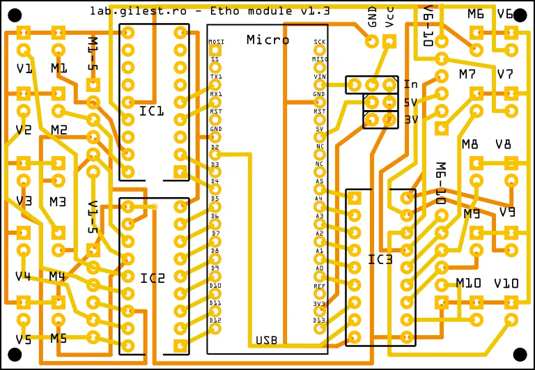
Each output connector has two pads: the upper, square pad is the positive rail (+) and the lower pad is the switched output of its Darlington array (−). The four 6-pin headers repeat the outputs of five connectors each, with the rail on pin 1 (the square pad); they are used only for the LED boards.
- Fit a board-side JST connector (Farnell 1516276) in each of the valve positions V1–V10 and solder it from the back. Leave the four 6-pin headers empty, and the motor positions M1–M10 too, unless you build the motors and valves variant.
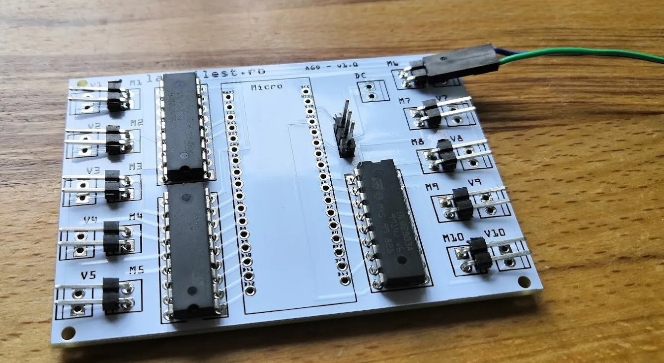
- Fit the three Darlington arrays with their inputs (pins 1–9) facing the Arduino: IC1 and IC2, on the left, with the notch pointing down; IC3, on the right, with the notch pointing up.
-
Solder the three arrays.
-
Fit straight pin headers in the jumper block, to the right of the Arduino: three pins in the row marked In, two in each of the rows marked 5V and 3V. Solder them, then fit one jumper link as described below these steps.
-
At the DC input, above the jumper block, fit a 2-pin 2.54 mm connector for the power leads, or solder the leads straight into the pads later. Vcc (+) is the right-hand, square pad and GND (−) the left-hand pad.
-
Check once more the orientation of the arrays, then place the Arduino Micro on its footprint with its USB connector pointing down, towards the USB mark at the bottom edge.
-
Solder the Arduino directly to the board. A socket would make it removable, but a tall socket does not fit in the case, and a soldered Arduino cannot easily be taken off again.
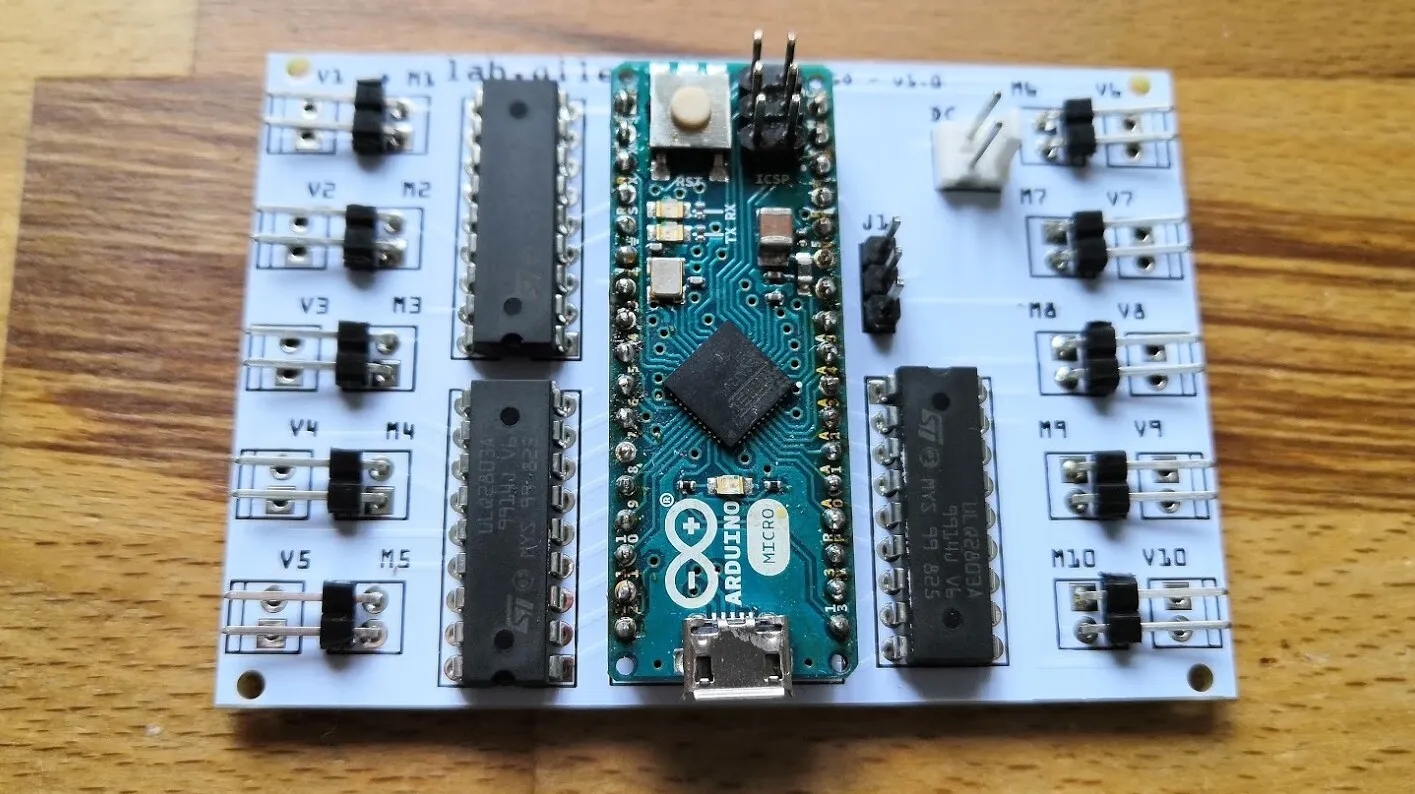
Jumper block. The jumper block chooses the supply of the outputs. Its pins:
| Row | Left pin | Middle pin | Right pin |
|---|---|---|---|
| In | Arduino VIN | DC input (+) | outputs’ rail |
| 5V | — | Arduino 5 V | outputs’ rail |
| 3V | — | Arduino 3.3 V | outputs’ rail |
The outputs have no supply until a link joins one of the rows to the rail:
| Link | Effect |
|---|---|
| In, middle–right | The DC input powers the outputs. This is the normal setting for motors, valves and LEDs. |
| In, left–middle | Not used: it would feed the DC input to the Arduino’s VIN, which needs 7–12 V. The Arduino takes its power from the ethoscope’s USB. |
| 5V, middle–right | The outputs run from the Arduino’s 5 V, which comes from the ethoscope’s USB port. For small loads only. |
| 3V, middle–right | The outputs run from the Arduino’s 3.3 V regulator. For small loads only. |
This module uses the In link, middle and right pins: the valves run from the DC input.
The firmware drives each valve connector from one Arduino pin. The motor connectors M1–M10 sit on the odd channels and are unused on the valves-only version.
| Connector | Firmware channel | Arduino pin, board v1.3 | Arduino pin, board v1.0 | Arduino pin, board v1.1 / v1.11 |
|---|---|---|---|---|
| V1 | 0 | D8 | D1 (TX) | D0 (RX) |
| V2 | 2 | D9 | D2 | D2 |
| V3 | 4 | D10 | D4 | D4 |
| V4 | 6 | D11 | D6 | D6 |
| V5 | 8 | D12 | D8 | D8 |
| V6 | 10 | D1 (TX) | D10 | D10 |
| V7 | 12 | D0 (RX) | D12 | D12 |
| V8 | 14 | A5 | A0 | A0 |
| V9 | 16 | A4 | A2 | A2 |
| V10 | 18 | A3 | A4 | A4 |
Older boards
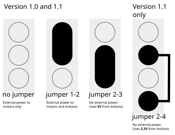
Section titled “Older boards”The module also works on boards made from the version 1.11 Gerber files or the version 1.0 Gerber files. Set PCBVERSION 11 in the firmware for a v1.1 or v1.11 board and PCBVERSION 10 for a v1.0 board (see Firmware). These boards have the same M and V connectors, with the square pad on the rail, but no 6-pin headers and no jumper block. Their supply is set on a single-row jumper, J1: left open, the DC input powers the outputs; linked 1–2, the DC input powers the outputs and the Arduino; linked 2–3, the outputs run from the Arduino’s 5 V; on version 1.1 and later, linked 2–4, from its 3.3 V.
Print the parts
Section titled “Print the parts”- Print the valve base at 0.15 mm layer height. It takes about nine hours and needs little or no support.
- Print two joiner input pipes for each odour you plan to use.
- For the valves-only version, print the cradle.
Print the parts in PLA. PLA softens at the temperatures an incubator reaches when it fails: ethoscopes have deformed when an incubator overheated. PETG resists heat better.
Not yet documented: print settings other than those given on this page.
Prepare the valves
Section titled “Prepare the valves”- Crimp a JST terminal (Farnell 1516301) onto each of the two wires of a valve.
- Push both terminals into a wire-side housing (Farnell 1516264).
- Repeat for all ten valves.
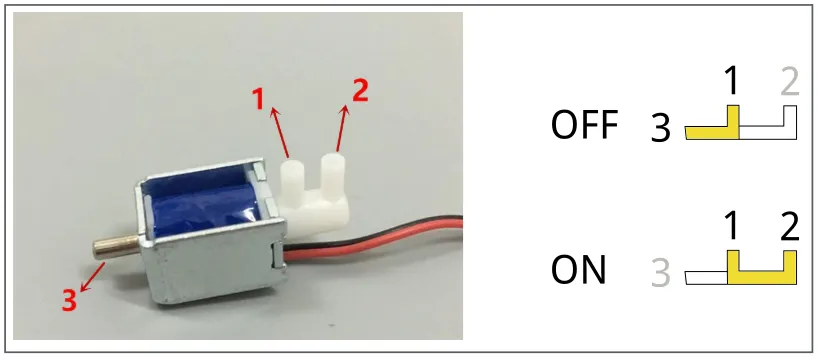
Each valve has three ports. When the valve is off, port 1 connects to port 3; when it is on, port 1 connects to port 2.
Assemble the module
Section titled “Assemble the module”-
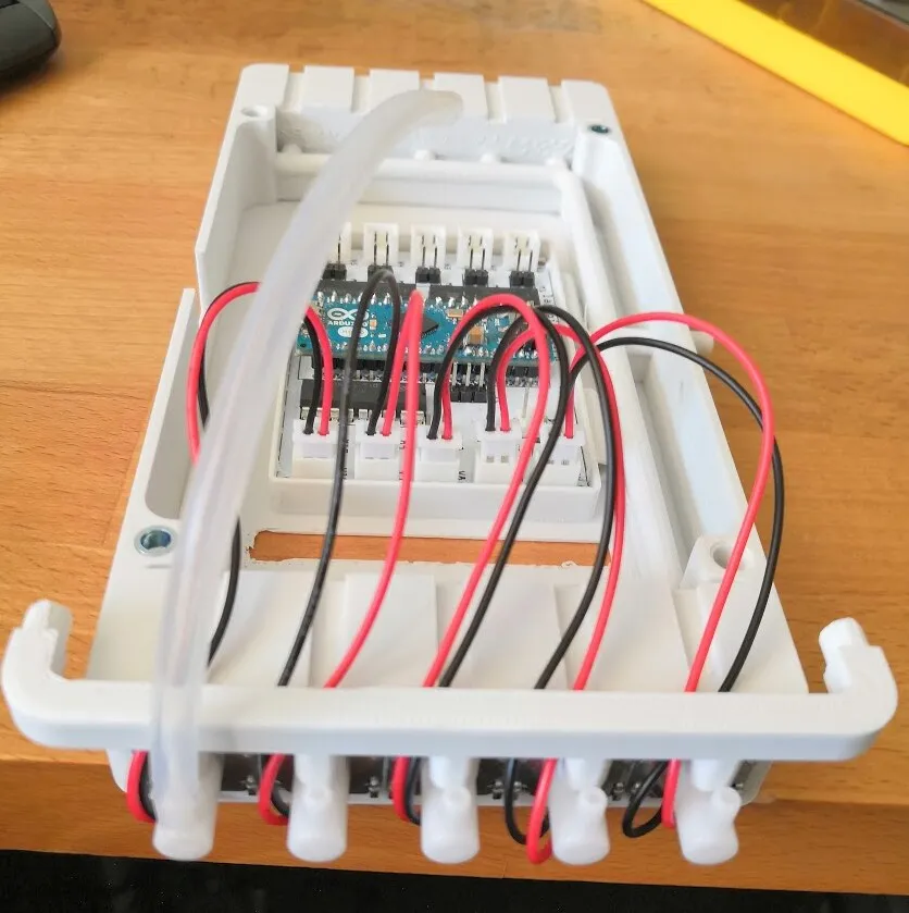
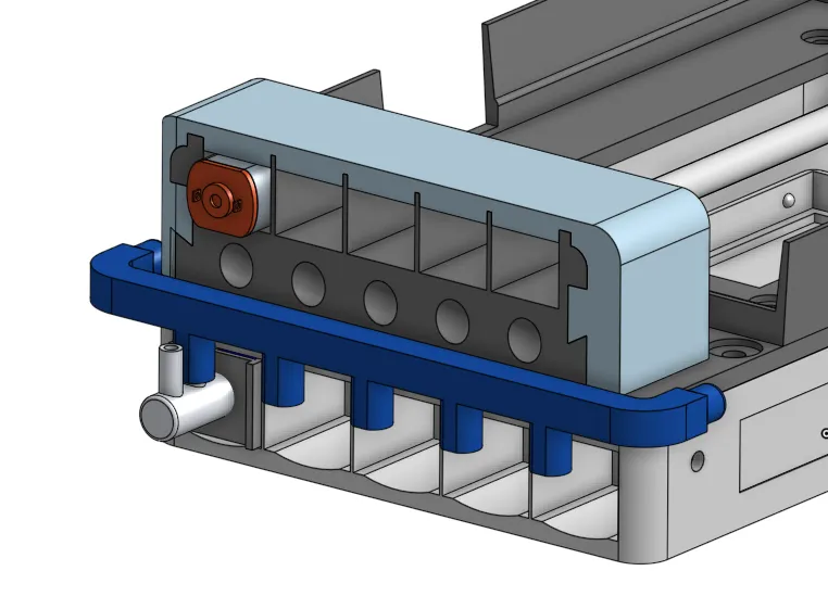
Fit the board in the valve base, as in the photograph at the top of this page.
-
Seat the ten valves in their slots in the valve base, five on each side.
-
Plug the five valves on one side into V1–V5 and the five on the other side into V6–V10, in slot order, with V1 and V10 at opposite ends of the module.
-
Slot a joiner input pipe onto port 1 of the five valves on each side.
-
On the valves-only version, fix the cradle on top of the valve base with the M3 nuts and screws: 12 mm screws with stand-offs or a spacer, or 20 mm screws. The variant takes the motor holder instead.
Plumb the module
Section titled “Plumb the module”Choose one of two configurations.
Regular configuration: the flies receive a puff only when their valve opens.
- port 1 → input pipe (air or odour)
- port 2 → flies
- port 3 → waste
Continuous flow: the flies always receive a flow, of air when the valve is off and of odour when it is on.
- port 1 → flies
- port 2 → odour input
- port 3 → air input
Continuous flow has two drawbacks. Unless it is collected, the odour leaves the tubes and builds up in the incubator. And the flow must be adjusted by trial, because the flies are sensitive to it and move less when it is too strong.
For the regular configuration:
-
Join the ends of the two joiner input pipes with 5 mm inner-diameter silicone tube. The joints are 5.5 mm in outer diameter, so the tube stretches tightly over them.
-
Cut one of the two joints and insert the T connector; this is where air or odour enters.
-
Connect the T connector to the odour container, or straight to the air supply for puffs of air.
-
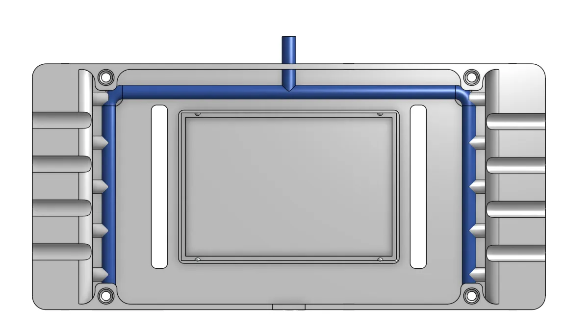
Fit silicone tube to the 5 mm waste outlet of the valve base. The waste channel, shown in blue below, collects the exhaust of all ten valves. A pump applying negative pressure to the outlet collects it better.
-
Connect port 2 of each valve to a steel tube. Pass the steel tube through the hole in line with its fly tube, in the cradle or, on the variant, in the cover with holes, and into the end of the fly tube. The air travels through tubing, so any valve can reach any tube; follow the table for your arena in Set up in the node. On the arena for long 5 mm tubes, V1–V5 feed the odd tubes 1, 3, 5, 7 and 9 and V6–V10 the even tubes 2, 4, 6, 8 and 10. On the 20-tube sleep arena, V1–V5 feed tubes 1, 3, 5, 7 and 9 and V6–V10 tubes 12, 14, 16, 18 and 20, the tubes that the motors of the variant turn.
-
Set the flow with the flow meter.
Use a different pair of joiner pipes for each odour. Joiner pipes can be reused between experiments with the same odour.
Make the odour containers
Section titled “Make the odour containers”- With a small wood bit, make two 3 mm pilot holes in the cap of a 60 ml jar, about 12 mm from the centre.
- Enlarge each hole with an 8 mm bit, then widen it until a push-in fitting (RS 176-1276) fits.
- Push a fitting through each hole and secure it from the inside with a 1/8 NPT locknut, tightened with a socket.
- Put the odour in the jar and close the cap.
- Wrap a couple of turns of Parafilm or grafting tape round the cap.
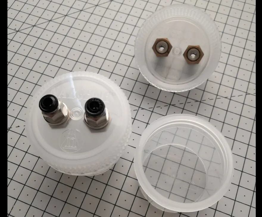
The two fittings are alike: connect either to the air supply and the other to the T connector.
The outputs take their power from the DC input, through the link on the In row of the jumper block (middle and right pins). Connect the power source to the DC input with + to Vcc (the right-hand, square pad) and − to GND.
USB-C. A USB-C socket, with its two leads in the DC input, takes 5 V from a USB charger. A USB-C charger switches its output on only for a device that identifies itself through the socket’s CC pins. If the module gets no power through a USB-C to USB-C cable, use a USB-A charger and a USB-A to USB-C cable. Use a charger rated 3 A: each valve draws 260 mA at 5 V, 2.6 A if all ten are open together.
- Link the In row of the jumper block, middle and right pins.
- Connect the two leads of the USB-C breakout board to the DC input, + to Vcc and − to GND.
Mount the module on the ethoscope
Section titled “Mount the module on the ethoscope”- Stand the ethoscope on the module.
- Connect the micro-USB cable from the Arduino to a USB port of the ethoscope’s Raspberry Pi. Do not connect any other USB serial device to the same ethoscope.
Variant: motors and valves
Section titled “Variant: motors and valves”This variant (firmware MODULE 1) carries the ten valves of the air delivery module and the ten N20 motors of the sleep deprivation module, so that the same flies can be woken by rotating their tube or by a puff. The motor holder sits straight on top of the valve base, in place of the cradle, so that the motors rest against the tubes. It is used with the 20-tube sleep arena only: the motors do not serve the arena for long tubes.
Additional parts
Section titled “Additional parts”| Part | Qty | Catalogue no. | Supplier | Notes |
|---|---|---|---|---|
| Right-angled PCB header, 2 pins | 10 | 251-8654 | RS | Motor connectors M1–M10. |
| N20 geared DC motor, 6 V, 200–240 rpm | 10 | 32778906874 | AliExpress | The 6 V version, run from 4.8–5 V; it draws about 25 mA at 4.8 V. |
| Two-core ribbon cable | 10 lengths | — | — | One lead per motor. |
| 2-way connector for the motor leads | 10 | 251-8171 (solder type) | RS | Or crimp housings Farnell 2226A-02 with two Farnell 2226TG crimp terminals each. |
| Motor holder (printed) | 1 | — | — | STL file, 93 × 189 × 26 mm. |
| Cover with holes (printed) | 2 | — | — | STL file, 85 × 21 × 28 mm; one for each row of five motors. Ten 3.2 mm holes, 6.5 mm apart, run through it in line with the tubes: the steel tube of each valve passes through the hole in line with its tube. |
| Motor shaft (printed) | 10 | — | — | STL file, 11 mm across and 10 mm tall, with a D-shaped bore for the motor’s output shaft. |
| Silicone tube, 10 mm inner × 12 mm outer diameter | 10 short pieces | B01N3YIQ0Y | Amazon UK | Grip sleeve for each shaft. |
| Standard sleep arena, rotating version, with twenty 5 mm glass tubes (VWR 201-1005) | 1 | — | — | The tubes in the wider slots rotate. Model on Onshape. The fixed version of the arena does not let the tubes rotate. |
Additional build steps
Section titled “Additional build steps”-
When soldering the board, also fit a right-angled 2-pin header in each motor position M1–M10, tilted slightly upwards on a fold of paper, and solder them from the back.
-
Solder a length of two-core ribbon cable, long enough to reach from the motor’s slot in the holder to its connector on the board, to each motor, with the cable leaving at a right angle to the motor body, and fit a 2-way connector to the other end.
-
Push a printed shaft onto the output shaft of each motor and slide a piece of the 10 mm silicone tube, cut to the 10 mm height of the shaft, over it.
-
Place the motors in the motor holder, five on each side, lying on their long side, and pass each cable through the hole underneath its slot.
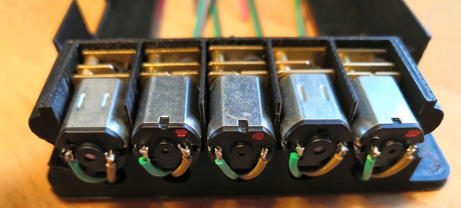
-
Plug the motors on one side into M1–M5 and those on the other side into M6–M10, in slot order: the slot under ROI 1, at the end of the arena with the empty black spot, goes to M1, and the slot under ROI 20, at the end by the ethoscope’s I2C power connector, goes to M10.
-
Fix the motor holder on top of the valve base with the M3 nuts and screws: 12 mm screws with stand-offs or a spacer, or 20 mm screws.
-
Fit a cover with holes over each row of five motors.
-
Plumb the valves so that every tube with a motor also gets air: V1–V5 feed the tubes in ROIs 1, 3, 5, 7 and 9, and V6–V10 those in ROIs 12, 14, 16, 18 and 20, the same tubes that M1–M10 turn.
| ROI | Motor (channel) | Valve (channel) |
|---|---|---|
| 1, 3, 5, 7, 9 | M1–M5 (1, 3, 5, 7, 9) | V1–V5 (0, 2, 4, 6, 8) |
| 12, 14, 16, 18, 20 | M6–M10 (11, 13, 15, 17, 19) | V6–V10 (10, 12, 14, 16, 18) |
| 2, 4, 6, 8, 10, 11, 13, 15, 17, 19 | — | — |
The motor connectors use these Arduino pins:
| Connector | Firmware channel | Arduino pin, board v1.3 | Arduino pin, board v1.0 | Arduino pin, board v1.1 / v1.11 |
|---|---|---|---|---|
| M1 | 1 | D3 | D0 (RX) | D1 (TX) |
| M2 | 3 | D4 | D3 | D3 |
| M3 | 5 | D5 | D5 | D5 |
| M4 | 7 | D6 | D7 | D7 |
| M5 | 9 | D7 | D9 | D9 |
| M6 | 11 | A2 | D11 | D11 |
| M7 | 13 | A1 | D13 | D13 |
| M8 | 15 | A0 | A1 | A1 |
| M9 | 17 | D13 | A3 | A3 |
| M10 | 19 | D2 | A5 | A5 |
Motors and valves both take their power from the DC input, through the same 5 V, 3 A supply.
Firmware
Section titled “Firmware”The firmware is the sketch ethoscope_multimodule.ino in the ethoscope repository, folder accessories/hardware/ethoscope_multimodule/. It needs no external libraries. Use version 1.6 or later, on the dev branch from 29 October 2026: earlier versions do not accept PCBVERSION 14. Flash it from a computer before you mount the module.
Get the sketch and set it up
Section titled “Get the sketch and set it up”-
Download the folder, for example with:
Terminal window git clone --depth 1 --branch dev https://github.com/gilestrolab/ethoscope.gitcd ethoscope/accessories/hardware/ethoscope_multimodule -
Copy the configuration template:
Terminal window cp versions.h.example versions.h -
Open
versions.hand set the two values:#define PCBVERSION 14 // 14 for a v1.3 board; 11 for v1.1 or v1.11; 10 for v1.0#define MODULE 2 // 2 = valves only; 1 = motors and valves
Flash with the Arduino IDE
Section titled “Flash with the Arduino IDE”- Open
ethoscope_multimodule.inoin the Arduino IDE. Keep it in its folder, next toversions.h. - Choose Tools → Board → Arduino AVR Boards → Arduino Micro.
- Connect the Arduino with the micro-USB cable and choose its port under Tools → Port.
- Click Upload.
Flash with arduino-cli
Section titled “Flash with arduino-cli”From the ethoscope_multimodule folder:
arduino-cli core update-indexarduino-cli core install arduino:avrarduino-cli board list # find the port, e.g. /dev/ttyACM0arduino-cli compile --fqbn arduino:avr:micro .arduino-cli upload -p /dev/ttyACM0 --fqbn arduino:avr:micro .Check the module
Section titled “Check the module”Open the serial monitor of the Arduino IDE (or any serial terminal) at 115200 baud, with lines ending in a newline, and send:
T: the module reports itself as JSON. For valves only, check for"AGO Odour Arousal Module","type":2and"valves":10; for the motors and valves variant,"AGOSD Sleep Deprivation and Odour Arousal Module","type":1,"motors":10and"valves":10. The version string readsFW-1.60;HW-14(HW-11orHW-10on an older board).D: the module switches on every channel in turn, from channel 0 to channel 19, for 500 ms each and 600 ms apart, about 12 seconds in all. On a v1.3 board set toPCBVERSION 14the order is V1, M1, V2, M2, … V10, M10. Listen for each valve clicking, V1 first and V10 last, 1.2 s apart; in the variant, each motor turns between two valves. This is the wiring check: a valve that clicks out of order is plugged into the wrong connector.P 0 500: valve V1 opens for 500 ms.P <channel> <ms>drives any single channel; the valve channels are 0, 2, 4, … 18 (see the table in Solder the board).- In the variant only,
A 5: all motors turn for 5 s.
H lists the commands. Two limits of the firmware matter for experiments: a duration in P can be at most 32,767 ms, and the module switches outputs in steps of about 50 ms, so shorter or finer timings are rounded up.
If Python and pyserial are installed, the test script in the same folder runs these checks for you:
python test_multimodule.py /dev/ttyACM0Once the module is on the ethoscope, the node shows the same information under Options → Module Info on the ethoscope’s page; its test button sends D.
Set up in the node
Section titled “Set up in the node”- Plug the module’s USB cable into the ethoscope and power the module. On the node, open the ethoscope’s page: the module shows as connected.
- Check it with Options → Module Info: it should report 10 valves (and 10 motors for the motors + valves variant).
- Click Start Tracking. Under Configure Stimulators, click Add Stimulator and set the Trigger and the Stimulus (Valve/odour pulse). Leave the active period empty to stimulate for the whole run, or give it a date range or a daily window.
- To change the protocol during a run, add further stimulators with their own active periods. If two periods overlap, the first stimulator in the list wins.
- Start the run. If the stimulus does not match the module (for example Motor pulse on an LED-only module), the run does not start and the error names the module and what it drives.
| Setting | Default | What it does |
|---|---|---|
| Trigger | Inactivity, Activity, Midline crossing or Periodic | Inactivity probes arousal of still flies; Periodic puffs at fixed intervals |
| Minimal inactivity time | 120 s | Inactivity trigger |
| Minimum seconds between stimulations | 60 s | Refractory period after each puff |
| Stimulus | Valve/odour pulse | Opens the tube’s valve |
| Pulse duration | 1000 ms | How long the valve stays open |
| Probability the stimulus will be delivered | 1.0 | Below 1, some decisions are logged but not carried out (sham controls) |
With the motors + valves variant, add one stimulator with Motor pulse and one with Valve/odour pulse, each with its own active period.
Which tubes are stimulated. On the arena for long 5 mm tubes all ten tubes are served:
| Tube (ROI) | 1 | 2 | 3 | 4 | 5 | 6 | 7 | 8 | 9 | 10 |
|---|---|---|---|---|---|---|---|---|---|---|
| Valve connector (channel) | V1 (0) | V6 (10) | V2 (2) | V7 (12) | V3 (4) | V8 (14) | V4 (6) | V9 (16) | V5 (8) | V10 (18) |
On the 20-tube sleep arena the valves serve the same ten tubes as the motors, so on the motors + valves variant each of these tubes gets both air and rotation. The other ten tubes are unstimulated controls:
| Tube (ROI) | 1 | 3 | 5 | 7 | 9 | 12 | 14 | 16 | 18 | 20 |
|---|---|---|---|---|---|---|---|---|---|---|
| Valve connector (channel) | V1 (0) | V2 (2) | V3 (4) | V4 (6) | V5 (8) | V6 (10) | V7 (12) | V8 (14) | V9 (16) | V10 (18) |
| Motor connector (channel), variant | M1 (1) | M2 (3) | M3 (5) | M4 (7) | M5 (9) | M6 (11) | M7 (13) | M8 (15) | M9 (17) | M10 (19) |
Troubleshooting
Section titled “Troubleshooting”| Symptom | Likely cause | Fix |
|---|---|---|
Compiling stops with versions.h: No such file or directory |
The configuration file was not created | Copy versions.h.example to versions.h in the sketch folder and set PCBVERSION and MODULE. |
Compiling stops with Invalid MODULE or Invalid PCBVERSION |
A value outside the accepted ones | Use a MODULE from 0 to 4 and a PCBVERSION of 10, 11, 12, 13 or 14. |
T answers, but no valve clicks with D |
No supply on the outputs: no link on the In row of the jumper block, the power source off or flat, or a fault in the DC input wiring | Fit the link on the In row (middle and right pins). Check the power source and the DC input: + to Vcc, − to GND. |
T answers, but none of the valves served by one array clicks |
Darlington array fitted the wrong way round or badly soldered | Check the orientation (IC1 and IC2 notch down, IC3 notch up) and the solder joints. |
P 0 500 does not open V1, or under D the valves click out of order although each is on its own connector |
PCBVERSION does not match the board |
On a v1.3 board set PCBVERSION 14, except for the 20-LED module with two LED boards, which takes 12 (or 13). Set 11 for v1.1 or v1.11 and 10 for v1.0, then flash again. |
Under D, valves click out of order |
Valve leads plugged into the wrong connectors | Re-plug them so that they click V1 to V10 in slot order. On the left side of the board the labels sit below their connectors, on the right side above. |
| One valve never clicks | Crimp or connector fault, or a faulty valve | Send P <channel> 1000 for that valve; re-crimp the lead, or replace the valve. |
| Valves click weakly or not at all when several open together | Supply too weak for the valves | Use a 5 V supply rated 3 A. |
| Flies move less than expected throughout the experiment (continuous flow) | Flow too strong | Lower the flow until the flies’ activity is normal. |
| Odour builds up in the incubator | Exhaust not collected (continuous flow, or waste outlet left open) | Use the regular configuration, and collect the waste through the outlet, ideally with a negative-pressure pump. |
| Traces of a previous odour | Joiner pipes shared between odours | Use a separate pair of joiner pipes for each odour. |
| The node does not detect the module (Add Stimulator stays disabled) | USB cable for charging only, or an Arduino clone with a different USB ID | Use a data cable. For a clone, find its vendor:product ID (for example with lsusb) and add it to /ethoscope_data/config/modules.json on the ethoscope, e.g. {"micro_clone": {"name": "Arduino Micro clone", "family": "arduino", "model": "micro", "used_for": ["mAGO"], "id": ["1a2b:3c4d"]}} with your ID in place of 1a2b:3c4d. |
| Commands sometimes go to the wrong device | More than one USB serial device on the ethoscope; the software picks one of them arbitrarily | Leave only the module connected. |
| Puffs shorter than about 50 ms are longer than set | The firmware switches outputs in steps of about 50 ms | Use pulses of 50 ms or more. |
| The Update Firmware button in Module Info fails | Ethoscope software older than 29 October 2026 cannot compile this sketch | Update the ethoscope software, or flash from a computer, as in Firmware. |