

Servo sleep deprivation module (legacy)
What it does
Section titled “What it does”Ten 9 g hobby servos sit in a printed chassis under the arena. Each servo carries a printed pulley linked to one tube by a nitrile O-ring, so that turning the servo turns the tube. When the ethoscope decides to act, the servo swings to +80°, to −80°, to +80° again and back to centre, in about one second; both the angle and the speed of the swing can be set. The servos are driven by a Lynxmotion SSC-32U servo controller, connected to the ethoscope by USB and powered through a second USB cable. This is the module described in Geissmann et al. 2017, PLoS Biology.
This page documents version 1, the module of the 2017 paper, which is the only version with complete assembly and wiring notes. The files of a version 2 chassis, which uses the same electronics, are attached under Parts without assembly notes.
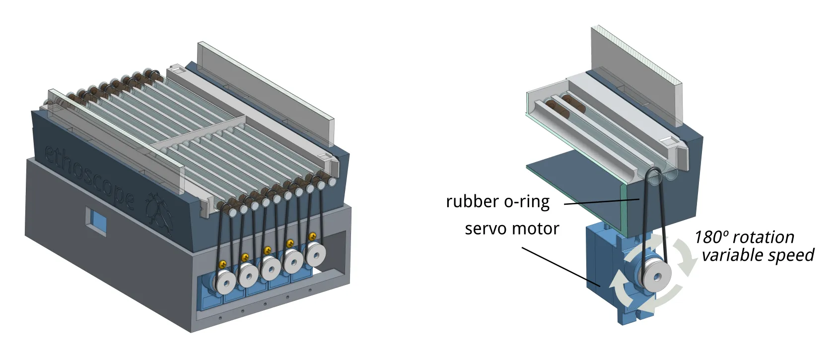
The ethoscope software still contains the stimulator for this module (SleepDepStimulator), but it is hidden: it appears only on ethoscopes flagged as experimental, and the node’s Add Stimulator button cannot select it.
What you need
Section titled “What you need”| Part | Qty | Catalogue no. | Supplier | Notes |
|---|---|---|---|---|
| 9 g micro servo, 4.8 V, standard (not continuous rotation) | 10, plus spares | RB-Fit-03 | RobotShop | Any 9 g servo of this standard. The continuous-rotation version needs different software and gives too weak a stimulus. Servos fail often: buy more than you need. |
| Lynxmotion SSC-32U servo controller, USB version | 1 | RB-Lyn-850 | RobotShop | Not the Bluetooth version. |
| Nitrile O-ring, 22 mm inner diameter × 1.5 mm cross-section | 10 | — | Polymax | Links each pulley to its tube. Any O-ring of the same size. |
| Pulley screw, 2 × 6 mm | 10 | — | — | Or the smallest screw supplied with each servo. |
| Servo screw, 2 × 10 mm | 20 | — | — | Two per servo; or the two remaining screws supplied with each servo. |
| Superglue | — | — | — | A drop to secure each pulley. |
| Chassis, version 1 (printed) | 1 | — | — | STL file, 92 × 126 × 39 mm. |
| Pulley (printed) | 10 | — | — | STL file, 11 mm across and 3.8 mm thick, grooved for the O-ring. |
| Cable sleeve or short zip ties (optional) | 2 sleeves or 4–6 ties | — | — | To bundle the servo wires, five at a time. |
| USB cable, USB-A to mini-USB, 30 cm | 1 | — | — | Data: SSC-32U to the ethoscope’s Raspberry Pi. |
| USB cable, USB-A to micro-USB | 1 | 888-8811 | RS | Power: stripped at one end and wired to the SSC-32U’s VS1 terminal. |
| USB power supply, 40 W | 1 | — | Anker | Powers the servos through the power cable. |
| Standard sleep arena, rotating version, with twenty 5 mm glass tubes (VWR 201-1005) | 1 | — | — | The tubes in the wider slots rotate. Model on Onshape. The fixed version of the arena does not let the tubes rotate. |
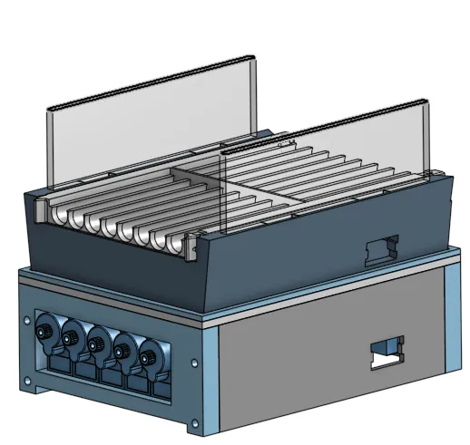
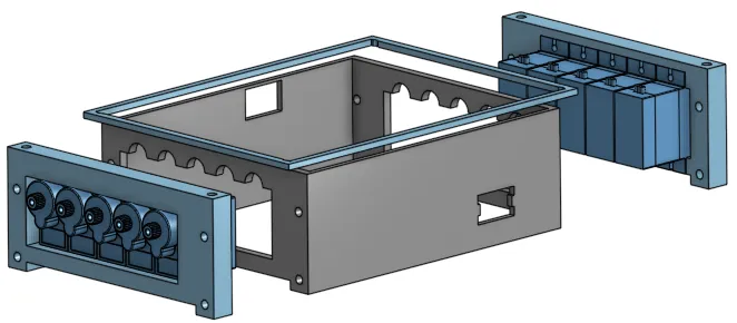
Version 2 chassis. Version 2 fits the newer modular dock, avoids the small screws and uses ready-made 3 mm foam board for the floor and for the base of the ethoscope. Print one main structure (STL), two outer walls (STL) and one crown (STL). The servos sit in slots in the outer walls and are held with M3 × 12 mm screws (RS 232-8164). The foam board is sold as, for example, Amazon UK B08M3FYVYW.
- Small Phillips screwdriver
- Small flat screwdriver, for the SSC-32U’s screw terminals
- Wire strippers
- Filament (FDM) 3D printer
- A computer with a serial terminal, to check the controller
Print the parts
Section titled “Print the parts”Print the chassis and ten pulleys of version 1, or the parts of the version 2 chassis.
Print the parts in PLA. PLA softens at the temperatures an incubator reaches when it fails: ethoscopes have deformed when an incubator overheated. PETG resists heat better.
Not yet documented: print settings other than those given on this page.
Assemble the servos
Section titled “Assemble the servos”-
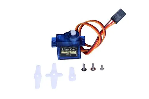
Set aside the plastic horns supplied with each servo; this module does not use them.
-
Fit a pulley onto the gear of each servo and fix it with the smallest supplied screw (or a 2 × 6 mm screw).
-
Add a drop of superglue between pulley and servo, keeping the glue away from the mechanism.
-
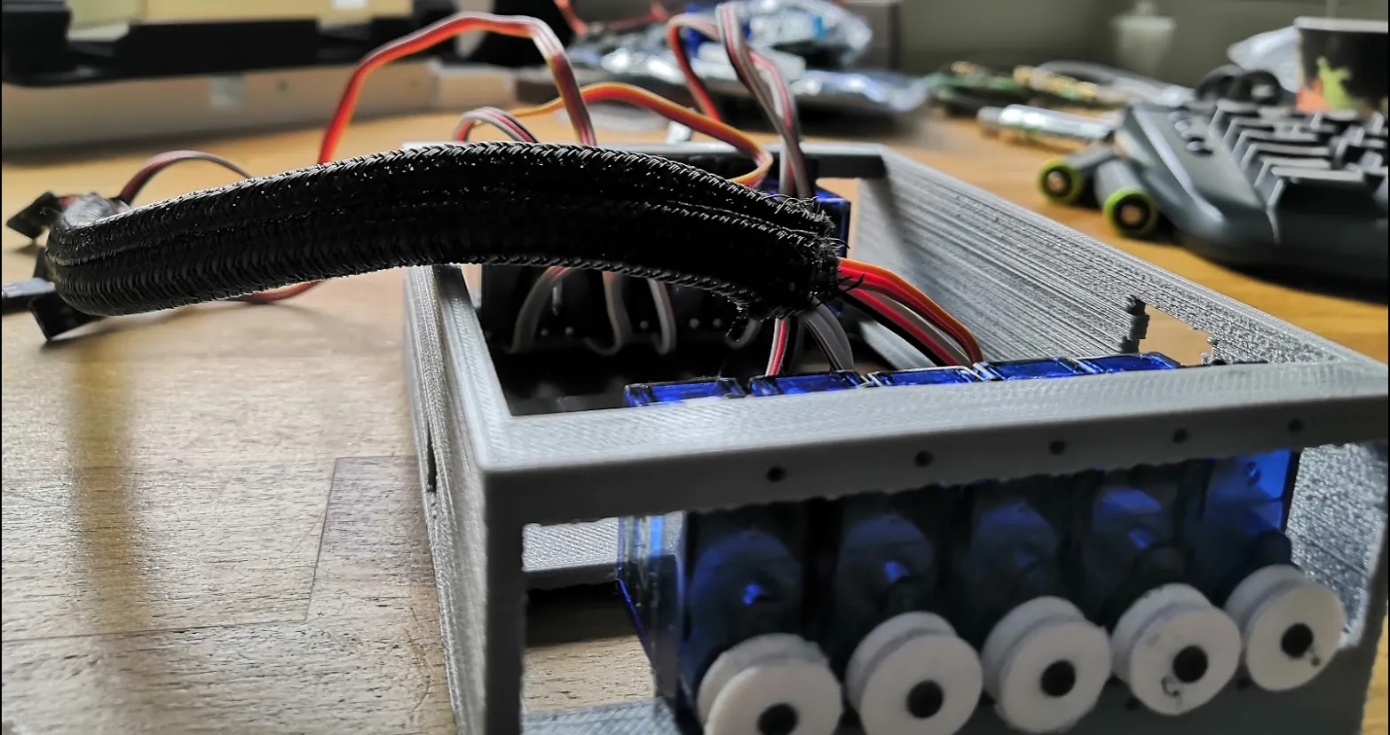
Fix each servo in the chassis with two screws, with the pulley facing the side on which the ethoscope will stand (not the fully open side).
-
Optionally, bundle the wires of each row of five servos with a cable sleeve or two or three zip ties.
Wire the controller
Section titled “Wire the controller”-
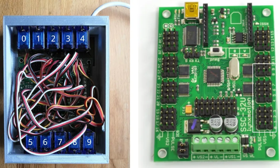
Number the servos 0 to 9 in the chassis, as in the photograph below.
-
Plug servo 0 into pin 0 of the SSC-32U, servo 1 into pin 1, and so on to servo 9 on pin 9. On each pin, the servo’s ground wire (black or brown) goes on the pin nearest the edge of the board.
-
Strip the micro-USB end of the power cable to expose its red and black wires.
-
Screw the red wire (+5 V) into the left (+) terminal of VS1 and the black wire into the right (−) terminal.
-
Plug the power cable into the 40 W USB power supply.
-
Connect the 30 cm mini-USB cable from the SSC-32U to a USB port of the ethoscope’s Raspberry Pi. Do not connect any other USB serial device to the same ethoscope.
Use a black cable for data and a white one for power, so that the two cannot be confused.
Mount the module
Section titled “Mount the module”-
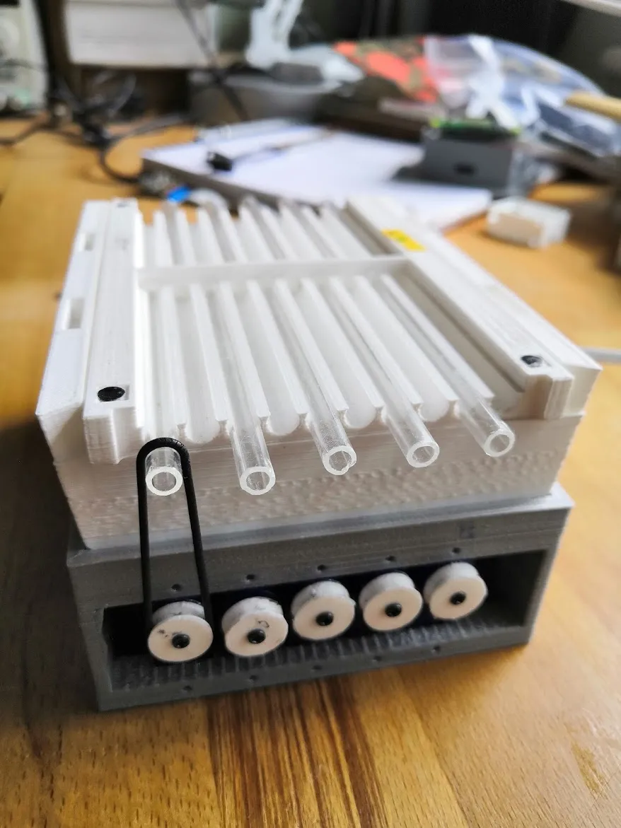
Prepare the arena and stand the ethoscope on the module.
-
Loop an O-ring from each pulley round its rotating tube. The O-ring should grip the tube, but not so tightly that it strains the servo shaft.
Firmware
Section titled “Firmware”There is no firmware to flash: the SSC-32U runs its own, and it ships set to 115200 baud, the rate at which the ethoscope talks to it.
To check the controller, open a serial terminal on its port (on Linux, /dev/ttyUSB0) at 115200 baud, with lines ending in a carriage return, and send:
# 0 P 2391 T 500: servo 0 moves to +80° in 500 ms.# 0 P 644 T 500: servo 0 moves to −80°.# 0 P 1518 T 500: servo 0 returns to centre.
The number after # is the pin (0–9), P the pulse width in microseconds and T the time of the move in milliseconds. The ethoscope maps −90° to 535 µs and +90° to 2500 µs, so these widths are the positions it uses. Repeat with pins 1 to 9 to check every servo.
Set up in the node
Section titled “Set up in the node”The servo stimulator is not offered by Add Stimulator. It appears only on an ethoscope flagged as experimental (an empty file /etc/ethoscope/isexperimental on the ethoscope), and that flag also makes the ethoscope behave as a machine without a camera for some options, so it is not suitable for routine experiments. A servo stimulator cannot be part of a sequence of several stimulators. For new work, rebuild the module on current hardware (below).
Troubleshooting
Section titled “Troubleshooting”| Symptom | Likely cause | Fix |
|---|---|---|
| No servo moves | Servo power missing or reversed | Check the power cable on VS1 (red to +, black to −) and its supply. |
| One servo does not move | Plug reversed or loose, or the servo has failed | Check that the ground wire is on the pin nearest the board edge; otherwise replace the servo. Servos fail often: keep spares. |
| The wrong servo moves | Servos not plugged in order | Plug servo 0 into pin 0, servo 1 into pin 1, and so on. |
| The servo moves but the tube does not, or the servo labours | O-ring too slack or too tight | Use a 22 × 1.5 mm O-ring that grips the tube without straining the servo. |
| A pulley works loose | Screw only, no glue | Refit it with the small screw and a drop of superglue. |
| The node shows a connected module and offers Add Stimulator, but nothing moves | The SSC-32U is detected as a module, but the stimulator that Add Stimulator creates sends commands for the current module board, which the SSC-32U does not understand | The module can be driven only by its own hidden stimulator, on an ethoscope flagged as experimental. |
| Commands sometimes go to the wrong device | More than one USB serial device on the ethoscope; the software picks one of them arbitrarily | Leave only the controller connected. |
Rebuilding it on current hardware
Section titled “Rebuilding it on current hardware”These notes describe how the module could be rebuilt around the Arduino module board and firmware used by the current modules. Nothing here has been built.
- Signal. A hobby servo needs a 50 Hz train of 0.5–2.5 ms pulses on a logic-level line. The Darlington outputs of the current module board are open-collector sinks for loads and cannot produce it. Take the servo signal lines straight from the Arduino Micro’s pins, on a new board or on headers, and power the servos from a separate 5–6 V rail sized for ten servos, with a ground shared with the Arduino. The supply jumpers of the module board play no part.
- Firmware. Add a sixth personality to the same sketch, for example
MODULE 5(“SERVO”), withMOTOR_COUNT 10so that the node shows motors, the servo pins in apins[]-style array, and the ArduinoServolibrary (the ATmega32U4 drives up to 12 servos per 16-bit timer). Keep the protocol: interpretP ch mson a motor channel as the rotate sequence that the ethoscope now runs itself (+80°, −80°, +80°, 0°; 350 ms per 180°), as a non-blocking state machine for each channel like the existingupdatePulseTrains(). Detach the servo (stop pulsing) after each sequence instead of holding it at 0°. Report the servos inT(for example"servos":10, or under"motors") and keepDas the test command. TheServolibrary comes with the Arduino IDE; witharduino-cliit may needarduino-cli lib install Servo. AddMODULE 5to the#errorguard and toversions.h.example. - Ethoscope software. If the servos sit at the N20 motor positions (ROIs 1, 3, 5, 7, 9, 12, 14, 16, 18 and 20) and are addressed on the odd channels, the current stimulator works unchanged with a motor pulse: it sends
P, and the pulse duration could set the sweep time. A cleaner route is a"servo"channel type inchannel_maps.pyand aServoRotateActionin theACTION_REGISTRYofactions.py, with a matching option in theaction_typelist. - Detection and updates. The ethoscope already recognises an Arduino Micro (USB ID 2341:8037), and the firmware updater recompiles whatever
MODULEthe board reports, so a newMODULEvalue needs no change to the Python code once the updater works. - Old code. Retire
LynxMotionInterface,SleepDepriverInterfaceand the servo stimulators only after old experiment configurations have been migrated.