

Module electronics
Since June 2020 the modules are built as stackable 3D-printed parts around one circuit board. The sleep deprivation module was the first to be redesigned this way, followed by the solenoid odour delivery module. All parts are in one Onshape workspace.
The printed parts
Section titled “The printed parts”A module is a base for the electronics with interchangeable parts stacked on top: for the sleep deprivation module, a motor holder and two covers that hold the motors down. The covers can be replaced, for example by covers with holes for access to the tubes or with room for five more motors, and further modules can be stacked below.
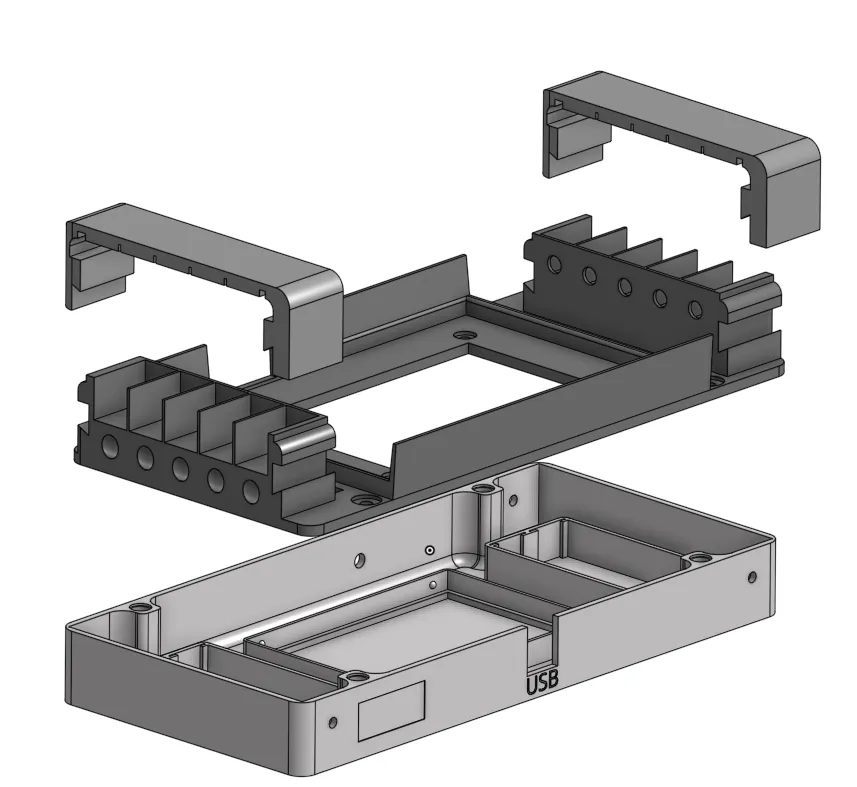
The footprint is small, to save space in the incubators. The distance between the motors and the floor plate is 35 mm, 7 mm less than in the earlier modules.
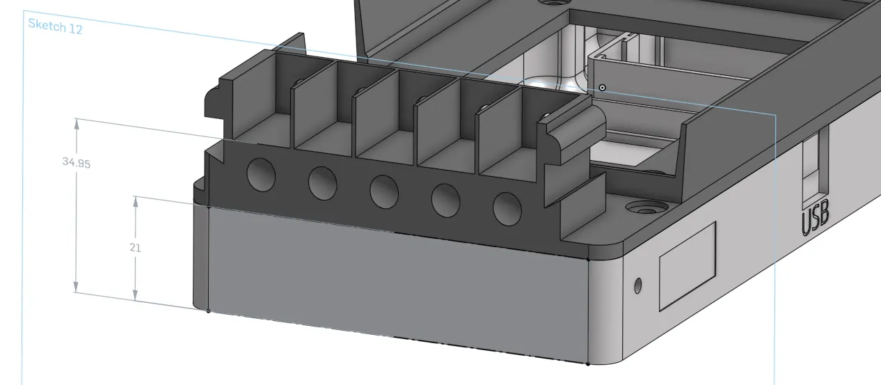
The parts print quickly and with little or no support, so they need little cleaning. At 0.20 mm layer height, the N20 motor holder and its base take about four hours each; the valve base is best printed at 0.15 mm and takes about nine hours.
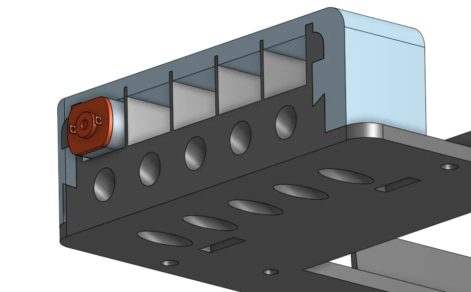
The motors lie on their long side. This reduces the strain on the soldered wires, a common cause of wires coming loose in earlier modules. The wires fold into the holes underneath and run straight down to the circuit board in the base.
Assembly hardware
Section titled “Assembly hardware”The parts sit on top of each other and are held together with screws:
- in each of the four corners of the base, either an M3 threaded insert (RS 138-893) that clips into place or an M3 nut (RS 837-262) slid in through a side slot. Nuts are better suited to the forces involved;
- M3 hex socket cap screws, 16 mm (RS 467-9818) or 20 mm (RS 467-9824). Longer screws (35 mm) can join a further module below;
- if a module is too cramped inside, M3 male–female standoffs between base and top: 10 mm (RS 606-686) or 5 mm (RS 806-6607).
The circuit board
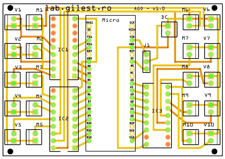
Section titled “The circuit board”The board carries an Arduino Micro (RS 771-7667) and three ULQ2803A Darlington transistor arrays (RS 168-8906, datasheet) wired to 20 Arduino output pins, digital and analogue. Each transistor can switch up to 500 mA, enough for N20 motors (example, 200–240 rpm, 25 mA at 4.8 V), solenoid valves (example, 260 mA at 5 V) or LEDs. The outputs are switched on and off (no PWM). The board was designed for the odour delivery module and is normally used with 10 motors (M1–M10) and 10 valves (V1–V10), five of each on either side, but anything that draws less than 500 mA can be connected.
An Arduino Nano Every (RS 192-7586) also fits, but it lacks the four pins furthest from its USB port: solder it so that the four positions near the “Micro” label (two on each side) stay free.
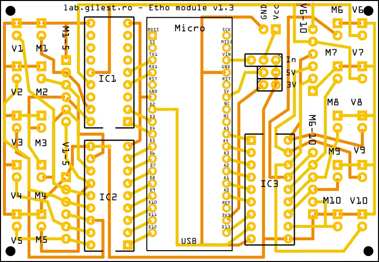
The board is 78 mm × 54 mm; order it as a two-layer board, 1.6 mm thick. It clicks into its support in the base without screws (the fit can be very tight on some printers).
- Gerber files, board ago_darlington_MICRO v1.11 (March 2026)
- Gerber files, board version 1.0 (March 2020)
Power and jumper J1
Section titled “Power and jumper J1”The motors can draw power from the Arduino’s 5 V supply, for small loads such as LEDs, or from an external supply, which can also power the Arduino. Jumper J1 (shorted with RS 251-8503) selects the option; see setting the jumper.
Connectors
Section titled “Connectors”- Valves: JST connectors with 2.54 mm pitch (Farnell 1516276) on the board; on the wires, housings Farnell 1516264 and crimps Farnell 1516301.
- Motors: PCB headers, straight (RS 251-8632) or right-angled (RS 251-8654).
- Arduino: soldered directly to the board through ordinary single-row headers (for example RS 173-0939, 20-way).
- A PA-09 crimping tool is recommended for the crimps.
Versions
Section titled “Versions”-
1.0 (March 2020): first version.
-
1.1 (July 2020): J1 can also power the circuit from the Arduino’s 3.3 V; the DC connector is rotated by 90 degrees; M1 and V1 are numbered consistently with the other channels.
-
1.3 (March 2026): the CONN pins of the Darlington arrays are connected to Vcc; four aliases of the motor and valve connectors can be wired with 6-pin cables (Vcc and five signals); a cleared jumper area.
Firmware
Section titled “Firmware”The firmware, ethoscope_multimodule.ino, is in the ethoscope repository and needs no external libraries. Before compiling, copy versions.h.example to versions.h and set two values:
#define PCBVERSION 10 // 10 = v1.0, 11 = v1.1, 12 = v1.2/1.3#define MODULE 0 // 0=SD, 1=AGOSD, 2=AGO, 3=mAGOLED, 4=LEDThen upload it to the Arduino with the Arduino IDE or arduino-cli. The module types and the commands the firmware accepts are listed in the modules overview.
Fitting the module
Section titled “Fitting the module”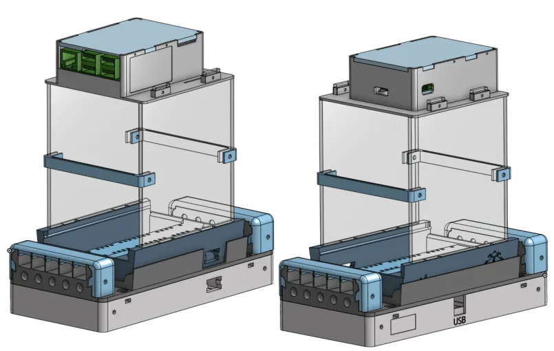
Mind the orientation of the module under the ethoscope (see also mounting orientation). Modules built on this system: the sleep deprivation module and the odour delivery modules.