

Four-way olfactometer
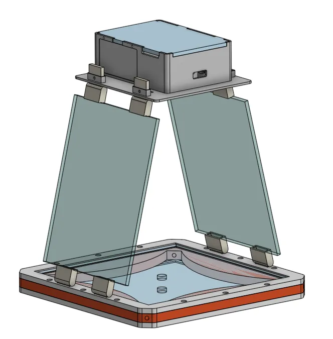
The olfactometer is an ethoscope with a different base. The base adapts the design of Lin et al. (2016), JoVE, doi:10.3791/54346, whose supplementary material includes detailed drawings of the arena. As that paper explains, the four-quadrant olfactometer was first developed to study the olfactory responses of individual parasitic Hymenoptera, and later adapted to individual Drosophila.
The arena
Section titled “The arena”The proportions and measurements of the paper are adapted in a 3D-printable model. Print the arena in CPE (RS 134-8174 for black) or PETG (example): they withstand odours better and are easier to clean.
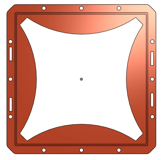
The vertices of the arena are 179 mm apart. The square inscribed in the arena has a side of 98 mm, smaller than in Lin et al. (137 mm), and the acrylic plates measure 146 mm instead of 220 mm; the proportions are the same.
The arena is clamped between two laser-cut acrylic plates, 3 mm thick and 146 mm square, held in place by a printed frame. At 146 mm, one 300 × 500 × 3 mm sheet (RS 434-295) gives six plates. Laser-cutting files for the plates (ZIP).
On both faces, a groove in the arena takes a gasket of 1.6 mm nitrile O-ring cord (RS 159-1478), cut to length and pressed in. The stack is closed with M4 nylon fasteners: 25 mm screws (RS 527-713), wing nuts (RS 292-596) and washers (RS 525-745). The four rectangular slots on the sides take printed adaptors, angled at 166 degrees, for two long laser-cut walls: the same walls used for ethoscopes with the camera v1, at 130 mm (adaptor on Onshape).
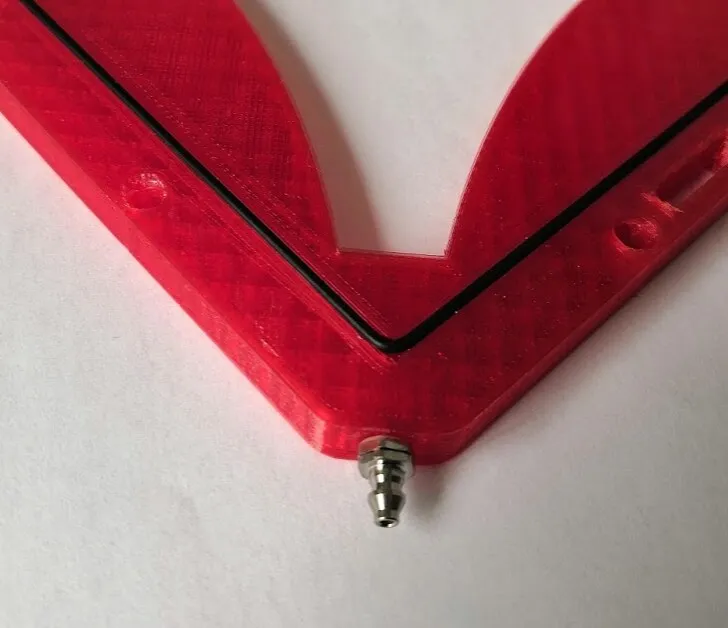
Air enters at the four corners. Fit each with an M3-threaded barbed connector (RS 768-1612) or an M3 push-in pneumatic connector: RS 176-1397 for 3 mm tubing, or RS 210-086 for 4 mm tubing with flow control.
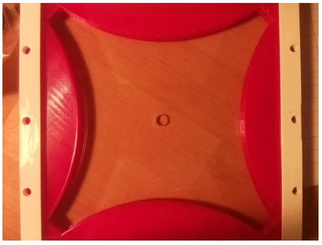
The bottom plate has a central hole of 6.1 mm, for extracting odours by vacuum, sized so that an M7 thread can be cut in it. The hole connects to 4 mm push-in nylon tubing (RS 483-4914) through an M7 elbow adaptor (RS 176-1341).
Tubing, fittings and odour jars
Section titled “Tubing, fittings and odour jars”- Tubing: PTFE is recommended, as it is more inert than nylon and reacts less with odours. PTFE is hydrophobic and nylon hydrophilic, so the solvent also matters. The barbed connectors take tubing of 3 mm inner diameter and the push-in outlet tubing of 4 mm outer diameter, so VWR 228-4138 fits both. The same tube is used for Bowden extruders on 3D printers and is sold far more cheaply for that use (example).
- Joints: push-in fittings for 4 mm outer diameter (RS 916-0899 tee, RS 916-0870 straight, RS 916-0915 Y) or for 3 mm inner diameter (RS 317-768 tee, RS 419-7259 Y). They are also sold by general marketplaces (example).
- Non-return valves: needed in the circuit; the lab uses RS 367-0618 (4 mm push-in).
- Odour jars: 60 ml jars with plastic screw caps (VWR 216-8203P). Drill the caps to take either check valves (RS 144-2693) or straight male connectors (RS 176-1276), secured with 1/8” NPT locknuts (TB73L-18), then coupled to one-way valves (RS 367-0618). See also making odour containers.
For illumination from below, a drawing light box (A3 or A2) can shine through the arena.
Measuring airflow
Section titled “Measuring airflow”The lab uses Tetra APS aquarium pumps: the APS 150 (nominal 150 L/h) or the APS 50 (nominal 50 L/h, measured pressure 2.7 PSI). Lin et al. suggest 100 ml/min per inlet, that is 6 L/h per inlet or 24 L/h in all, about half of what the APS 50 delivers.
To measure the flow precisely, use either:
- a digital flow meter, such as the Honeywell AWM3100V; or
- a digital differential pressure sensor, such as the NXP MPX5500DP (0–500 kPa).
Pressure sensors are inexpensive and flow meters much less so. One approach is to calibrate the pressure sensors against a flow meter, then use the pressure sensors to adjust the flow. The flow rate can also be calculated from the pressure, the size of the tubing and the density of the medium. The manufacturers’ datasheets give the pin-outs and response curves.
Code for reading the MPX5500 with an Arduino: MPX5500Sensor on GitHub.
Pressure sensor assembly
Section titled “Pressure sensor assembly”The Arduino carries a SainSmart LCD keypad shield with a 16×2 display; both sit in a printed case. The four MPX sensors share +5 V and ground, and their outputs go to pins A1 to A5 of the Arduino. The sensors have their own case.
Switching the flow automatically
Section titled “Switching the flow automatically”The Raspberry Pi of the ethoscope can switch the airflow on and off through a GPIO pin and a transistor. You need a logic-level MOSFET that withstands at least 300 mA (the lab uses RS 669-7717), a solenoid valve (the same as in the odour delivery module) and jumper wires to the GPIO header. Use pins 4 (5 V), 6 (ground) and 12 (GPIO 18, which switches the MOSFET).
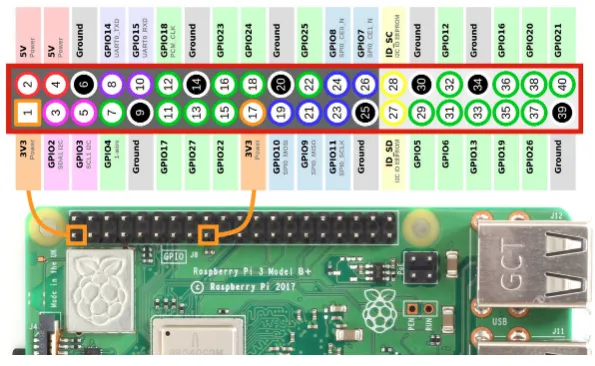
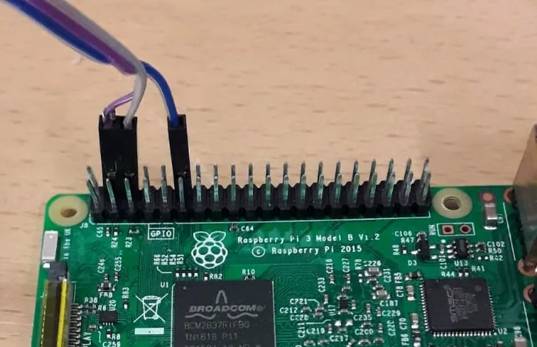
On the ethoscope, pinctrl set 18 op dh opens the valve and pinctrl set 18 op dl closes it. A script can run a whole protocol: this one waits five minutes for habituation, delivers air or odour for five minutes, waits two more minutes, then beeps:
#!/bin/bashdateecho "Habituation: waiting five minutes"sleep 5mecho "Valve open for five minutes"pinctrl set 18 op dhsleep 5mpinctrl set 18 op dlecho "Delivery finished: waiting two minutes"sleep 2mecho -en '\007'dateecho "You can stop the video recording now"Start a video recording from the node, then log in to the ethoscope from the node with ssh and run the script.
Measuring the odour received (experimental)
Section titled “Measuring the odour received (experimental)”Possible sensors, both I2C, which can be read by an Arduino or by an ESP8266 with an I2C shield:
- Seeed Studio Grove VOC and eCO2 gas sensor (SGP30), 101020512 (Mouser, RS 184-5085). It should detect several odours, including acetic acid, once a normalisation curve has been measured.
- Seeed Studio Grove CO2, temperature and humidity sensor (SCD30), 101020634 (RS 188-7076).